These will be uploaded soon.
Thursday, June 24, 2010
Rendering
Rendering involves setting the scenes look and feel by adding colour, textures and lighting.
Unfortunately, I have only looked briefly into these but feel that I have gained a basic understanding of how to set them.
The following is some notes I have gathered on rendering scenes in Maya from the Getting Started with Maya tutorial book.
In Maya, rendering refers to the process of creating bitmap images of your scene
based on the various shading, lighting, and camera attributes that you set.
When rendering, Maya takes into account all of the various objects and scene
attributes, and performs mathematical calculations to produce the final image
or image sequence. Once you render a sequence of images, you can then play
them back in sequence, producing an animation.
Rendering involves many components to produce an image:
■ Shading materials and textures
■ Lighting and shadows
■ Cameras and animation
■ Rendering method
■ Visual effects
Material Description
Lambert: Creates a matte surface without specular
highlights. Lambert is the default shading
material.
Blinn: Creates a shiny surface with specular
highlights, often used to simulate metallic
surfaces.
From the Rendering menu set, select Lighting/shading > Assign New
Material > Lambert or blinn (depending on the effect you want).
Maya renderers
Software rendering can take seconds or minutes to render a single frame of
animation from your scene, depending on the complexity of surface geometry,
shaders, lighting and other visual elements present in the scene.
The following table outlines the different types of renderers in Maya and what
each is used for:
Maya’s Software renderer: A general purpose renderer with broad
capabilities. You can produce high-quality images with complex shading networks, including procedural textures and ramps.
Software rendering is computed through
your machine’s processor.
Interactive Photorealistic Rendering (IPR): A feature of Maya’s software renderer, used
to make interactive adjustments to the final rendered image. You can adjust shading and lighting attributes in real-time, and IPR automatically updates the rendered image to show the effects of your changes.
IPR is useful for tweaking an image before rendering to disk.
mental ray® for Maya® renderer: A general purpose renderer that includes exclusive, advanced rendering functionality, such as host and network parallel rendering,
area light sources for soft shadows, global illumination, and caustics (light patterns).
Maya Vector renderer : A specialized renderer used to produce stylized renderings (for example, cartoon, tonal art, line art, hidden line, wireframe) in various bitmap image formats (IFF, TIFF)
or in 2D vector formats (SWF, AI, EPS, SVG). The Maya Vector renderer is often used to render web-ready images.
Maya’s Hardware renderer: A general purpose renderer that uses your machine’s graphics card for computation. You can produce broadcast resolution images in less time than with software rendering, and in some cases, the quality may be good enough for final delivery.
The Render View window
When you render your scene the rendered image appears in its own window
called the Render View. By default, the Render View uses the same camera as
the Scene View (persp), but includes particular rendering capabilities.
Directional lights
Maya has many types of lights that simulate natural and artificial lighting. A
directional light uses parallel rays of light, as if illuminating from a very far
distance, to illuminate the scene. A directional light is often used to simulate
sunlight.
Spotlights
A spotlight emits light from a single point within a limited cone angle. You can aim a spot light in the direction you want the light to illuminate.
Shadows
Shadows are the darkened areas that appear on a surface when an object gets
in the path of a light source. Shadows are cast onto the area of a surface that
doesn’t directly receive light. Shadows ground the objects in your scene and
aid in defining their three-dimensional appearance. Shadows can add drama
to your scene.
Creating additional cameras in a scene
Elsewhere in this book, you’ve used the default perspective camera to examine
and render your modelling and animation work in progress. In some situations,
it is convenient to create and use additional cameras.
For example, you might want to render the scene from two different camera
views to compare the results. Alternatively, you might want to use the default
camera for interactive modeling and animation and the second camera strictly
for rendering the scene. In the next steps, you create an additional camera
and manipulate its view of the scene.
To create a second camera for the scene
1 Select Create > Cameras > Camera. This creates a perspective camera with
an icon representing it at the center of the grid.
Animating camera moves
In Maya, the camera can be animated. You can set keyframes for the camera
moves the same as for other objects in your scene.
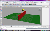
I decided to "batch render" a piece of my animation. The notes stated that this would require a lot of the computers processing power, so I only decided to render the first 50 frames.
Batch rendering a sequence of animation frames
After you model, animate, and color your scene, you set several Render Settings
options and then use the software renderer to batch render part or all of the
animation’s range of frames to files on disk. Each file represents a single frame
(image) of the animation.
After going through the process of setting it up to batch render it states:
Batch rendering 50 frames of a simple scene takes a few minutes. A
complex scene may take hours per frame, depending on the speed of
your computer.
Mine was not that complex but does contain a lot of polygons.. It took 20 minutes for these 50 frames to render and even then, they are not saved as one file, but 50 separate files each of a rendered frame.
Monday, June 7, 2010
Character Setup
In this lesson, you learn the techniques for creating a simple skeleton for a
human character. You will learn how to:
■ Create joints for a character.
■ Name joints in the Hypergraph.
■ Use symmetry when creating a character.
■ Parent joints into an existing skeleton.
■ Use Inverse Kinematics (IK) techniques to pose a skeleton.
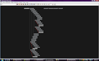
Hypergraph Hierarchy: This hierarchy represents the controls of the character skeleton. The top of the hierarchy is the main controller for the character. In this situation it's the lowest point of the back. Other sections are also main controller of their areas such as the arm connections which control the shoulders, elbows and wrists.
Lesson 2: Smooth Skinning.
In this lesson you learn how to:
■ Bind a skeleton using a smooth bind technique.
■ View and modify skin weights using the Skin Weights Tool.
■ Use influence objects to enhance the skin deformation of a character.
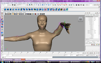
At first when the arm is moved it creates un-natural depressions around the shoulder and breast region.
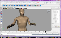
After applying the necessary weights to the area, the arm can be moved around and appear more natural. The above photo shows the arms in similar positions. The right one has been adjusted with the correct weights added where as the left one hasn't. This is most noticeable just under the characters armpit as it has created a large depression.
Lesson 3: Cluster and blend shape deformers.
In this lesson, you will be introduced to cluster deformers in order to shape
a characters mouth into a smile pose. You will learn to use the Blend Shape
feature so you can animate the face from a neutral pose to a smile. In this
lesson, you learn how to:
■ Select CVs in a region and create a cluster deformer.
■ Use the cluster deformer handle to adjust the position of a cluster deformer.
■ Use the Paint Cluster Weights Tool to refine the cluster weight values.
■ Create a Blend Shape deformer to control the blending between target
shapes.
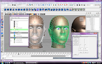
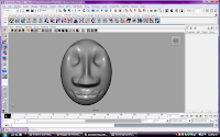
After adding weights around the mouth to make it appear as though the face is smiling.

Saturday, May 29, 2010
Animation
In this lesson, you learn how to:
■ Set keyframes for animatable objects and their attributes.
■ Use the Time and Range slider and Playback Controls to control the
playback.
■ Use keyboard shortcuts to set keyframes.
■ Use the Graph Editor to view animation curves.
■ Modify the animation of objects using the Graph Editor.
■ Set preferences to increase the playback quality.
By using the graph editor for this task, the motion of the ball had a more realistic curve/bounce to it.
Lesson 2: Set Driven Key.
In this lesson you learn how to:
■ Link the object attribute behavior between two objects which will link the
movement of one keyframed object to another with no keyframes assigned.
■ Use the Graph Editor to adjust the animation for the driven object.
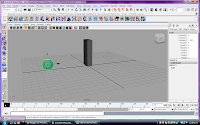
The motion created here happened when the ball moved towards and away from the oblong. When the ball got closer the oblong would rise up to a set position. Once the ball had passed through or moved away, the oblong returned to its original position.
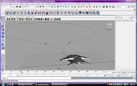
Lesson 3: Path Animation.
In this lesson, you learn how to:
■ Set an object to animate along a motion path using a NURBS curve as the
path.
■ Modify the timing and rotation of an object along a motion path.
■ Blend between keyframe and motion path animation.
This was very tricky to get right. The position of the air craft needed to be set to correct points for it to work properly. If I was to replicate this sort of animation from scratch I would need to plan out the placement before hand so that it would look realistic.
Lesson 4: Nonlinear animation with Trax.
In this lesson you learn how to:
■ Key animation sequences for use as nonlinear clips in Trax.
■ Create clips from your animation sequences for use in the Trax Editor.
■ Use the Trax editor to position, modify, and arrange clips in order to create and modify animation sequences in the scene.
■ Scale clips to modify the timing of an animation sequence.
■ Trim clips to remove unwanted motion.
■ Cycle clips to create motion that repeats.
■ Use the Graph Editor to modify the animation of a clip.
■ Use the Trax Editor to work with motion capture data.
■ Reuse clips using the Outliner and the Visor.
Part 1:
This was even harder to get right. There's so many more points that need to be considered and then setting them into trax was confusing.
Part 2:
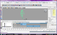
Moving an animated skeleton and getting them to rotate their direction.
This was using trax as well and already had some animation built into it. I would have preferred that it didn't so that I could learn how to combine a skeleton to a polygon shell and then animate it to move as I have had a lot of difficulty in trying to get this right.
Once the moving skeleton was in a trax clip it was easy to make it rotate.
Once the moving skeleton was in a trax clip it was easy to make it rotate.
Other Notes:
Blending clips
You can blend the animation between clips. Blends allow you to create smooth
transitions and mixes between different motions. A blend can be applied
between any two clips that overlap entirely, partially, or not at all. The best
results are obtained when blending between similar motions. In some
situations, a blend can be used to correct jump cuts. For more information
see Create and edit blends in the Maya Help.
Key into clip
You can set keyframes to alter the animation within a clip. This process is
called Keying into a clip. When you key into a clip, keyframes are placed at
the current time on all the animation curves in the selected clip. For more
information see Key into a clip in the Maya Help.
Time Warps
Time Warps let you change the timing of a clip without modifying the clip's
animation curves. You modify the Time Warp by editing the animation curve
that controls the warp. Time Warps can also be used to reverse the animation
in a clip. For more information see Create and edit time warps in the Maya
Help.
Visor and Outliner
Both the Visor and Outliner can be used to access clips. The Visor provides a
graphical interface to access other resources (such as clips, poses, shaders,
textures, and brushes) in your scene. The Outliner displays clips in a textual
manner, and is a bit more compact.
Audio clips
You can display and play multiple audio files in Trax allowing you to
synchronize your motion clips to specific audio events (sound effects, musical
notes, drum beats) in the audio file. Once you import an audio file into Trax,
you can then move and rename the audio clip. For more information see
Work with audio in the Maya Help.
Lesson 5: Inverse Kinematics.
In this lesson you learn how to:
■ Create and use hierarchies to define logical relationships between
animatable objects.
■ Combine the components of a 3D mechanical arm model into a
hierarchical grouping.
■ Construct a skeleton for use with IK.
■ Combine the skeleton with the mechanical arm model by parenting the
components into a hierarchy.
■ Create an IK system to allow the skeleton hierarchy to be posed.
■ Create a control object to manipulate the IK system.
■ Use constraints to control the position and orientation of components
within the IK system.
■ Limit the range of movement on the IK system.
■ Pose and set keyframes for the IK system.
■ Animate an object by constraining its motion to two or more objects.
*images to be put up.
Subdivision Surfaces.


In this lesson, you learn how to:
■ Convert a polygon surface to a subdivision surface.
■ Work with subdivision surfaces in Polygon Proxy Mode.
■ Split subdivision faces to create areas for more detail in a model.
■ Extrude the split faces to create fingers on the hand.
■ Work with subdivision surfaces in Standard Mode.
■ Change the Display Level when working in Standard Mode.
■ Add more detail to subdivision surface models using Refine Selected Components.
■ Create a crease along a vertex edge.
note: 194 normal mode, move tool, not working. I couldn't add the extra details to make the finger nails.
Monday, May 24, 2010
Other Interesting stuff
TBC
Lots of 3d video examples. Consist of very basic to extremely well constructed.
Sunday, May 23, 2010
NURBS Modeling
Lesson 1: Revolving a curve to create a surface.
In this lesson you learn how to:
■ Create a NURBS curve using the control vertices (CV) creation technique.
■ Use the grid for visual reference when modeling.
■ Determine the start and end points for a NURBS curve and its direction.
■ Create a revolved NURBS surface using the Revolve tool.
■ Change the display shading smoothness for a NURBS surface.
■ Edit a NURBS surface by editing its initial profile curve when it is linked
to the surface by construction history.
Lesson 2: Sculpting a NURBS surface.
In this lesson you learn:
■ Basic sculpting operations (push, pull, smooth, relax and erase) with the
Sculpt Geometry Tool.
■ How the density of isoparametric lines affects the surface detail possible
when sculpting.
■ How to increase the surface subdivisions on a NURBS surface to aid with
surface sculpting.
■ How to change the brush radius for the Sculpt Geometry Tool.
■ How Opacity and Max Displacement affect the sculpting operations.
■ How to import geometry from a pre-existing file into your current scene.
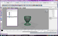
*Egg cup imported to scene
Lesson 3: Lofting curves to create a surface.

In this lesson you learn how to:
■ Modify the outline of a circle primitive by editing the position of its CVs.
■ Use the magnet snap feature.
■ Loft cross section curves to create a NURBS surface using the Loft tool.
■ Edit the form of an existing primitive object by moving its CVs.
■ Parent one object to another using the Outliner.
Subscribe to:
Posts (Atom)